Turning a Stepper Motor with Elixir
While the software for spinning a servo based on a reading from the proximity sensor was working great, unfortunately the servo motor turned out to be under-powered for the job at hand. I had combined parts from two different projects without a sufficient appreciation for the physics involved. I decided to switch to a more powerful stepper motor, so let’s see how to make that turn with Elixir.
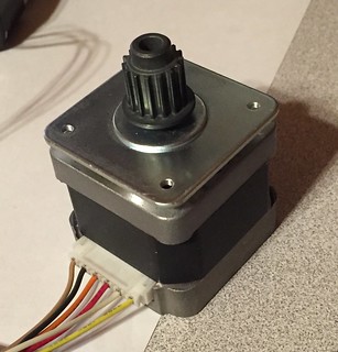
I returned to Adafruit and picked up a DC + Stepper Motor HAT and a battery pack. Their stepper motor was out of stock, and it was less powerful than the one in the Thurber Feeder 5000 so I grabbed this 44 oz-in stepper motor off of eBay.
Assembly
I did the soldering this time, and everything seems to work, so yay!
The next order of business is figuring out which wires from the motor go where. The motor didn’t come with a manual, you have to figure it out by measuring the resistance between each pair of wires, as described in this blog post.
Here are the values I measured:
| brown | black | orange | red | white | yellow | |
| brown | X | 4.4 | 8.8 | 0 | 0 | 0 |
| black | 4.4 | X | 4.4 | 0 | 0 | 0 |
| orange | 8.8 | 4.4 | X | 0 | 0 | 0 |
| red | 0 | 0 | 0 | X | 4.4 | 8.5 |
| white | 0 | 0 | 0 | 4.4 | X | 4.4 |
| yellow | 0 | 0 | 0 | 8.5 | 4.4 | X |
From this I can tell that the brown and orange wires should be connected to one set of inputs on the HAT, and the red and yellow wires to another.
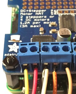
The Internet says that these motors either have four or five wires. Of course mine has six. I connected white and black to ground and it seems to work.
You can also see that I missed the fact that the blue blocks are supposed to lock together so they sit in a neat row. Oops.
Software
Like the Servo HAT, the DC+Stepper Motor HAT has a PCA9685 chip, so a lot of the Spinny code can be re-used. It also has a couple of TB6612FNG chips, which I originally thought I needed to know about, but it turns out that all we need to do is talk to the PCA9685 and it will deal with the rest.
I think a thorough study of the schematic for the Motor HAT would solve the mystery of why certain channels on the PCA9685 are used to do certain things, but for now I’m happy it works.
To run a stepper motor, you have to energize coil(s) in a pattern that causes the shaft to turn. Here is a diagram of which channels go with which input, and you can visualize turning either clockwise or counter-clockwise.
| A input 1 | ||
| channel 10 | ||
| B input 2 | B input 1 | |
| channel 12 | channel 11 | |
| A input 2 | ||
| channel 9 |
To do clockwise single-coil stepping, you turn on channel 10, then 11, then 9, then 12, and repeat.
To do clockwise double-coil stepping, you turn on 10 and 11, then 11 and 9, then 9 and 12, then 12 and 10. This is much stronger, (I can’t stop the motor from turning by holding the pulley the way I can when it’s single-coil,) but uses twice as much power.
The middle alternative is interleaved, where single- and double-coil steps are alternated. I haven’t tried this, but I believe it would be 10, 11 & 9, 12, 10 & 11, 9, 12 & 10, 11, 9 & 12, and repeat.
You can also do micro-stepping, which is left as an exercise for the reader. It involves setting two more channels (8 and 13, labeled PWM A and B respectively in the Python code) to different values.
IMPORTANT Once you are done, set all the channels to zero or do a software reset on the PCA9685. If you don’t, one or more coils will still be energized and the motor will get VERY hot. My battery pack doesn’t have a switch so when I realized this it was a bit of a scramble to find the code to turn the motor off.
The Python code that Adafruit provided is quite complex because it gives examples of all the different things you can do with both DC and stepper motors. I ended up deleting most of it and adding a bunch of print statements to concentrate on single-coil stepping one motor, which is how I figured out the pattern of what values it was sending to which channel.
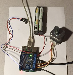
So, here is the Turny code, and here it is all assembled and working:
Conclusion
I can now turn a stepper motor from Elixir, and next I’ll replace the Servo code in the Cat Feeder project with this so that I can turn the stepper motor based on readings from the proximity sensor.
Then we’ll return to fabrication. I have a mount for the stepper motor, but the belt that came with it is way too long, and I still need a way to turn the augur. That’s probably going to involve a larger pulley and then 3D-printing a piece to interface between the large pulley and the augur.
The code for this example is available at https://gist.github.com/wsmoak/1e9d110b400118ec8642 and is MIT licensed.
Copyright 2016 Wendy Smoak - This post first appeared on http://wsmoak.github.io and is CC BY-NC licensed.